 Manage Reference Models
- General Overview
- Step-By-Step
- Tips and Tricks
- Related Tools
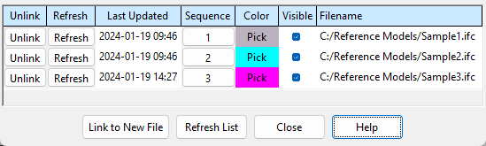
Unlink: Click the Unlink button associated with a particular reference model Filename to remove that reference model from your current Job.
Refresh: Click the Refresh button associated with a particular reference model Filename to adjust settings on the Linked Model ... Options window and re-import the reference model from that file. This is also useful when you have an updated reference model file with the same file name. Replace the old file with the new file at the same location and click the Refresh button to update the reference model. The entry made to Last Updated for the refreshed file updates to show the current date and time.
Last Updated: This field shows you the date (yyyy-mm-dd) and the time (hh:mm in 24-hour notation) when the reference model file was last imported using Link to New File, Import Model, or Refresh.
Sequence: Click the Sequence button to assign a different sequence to that particular reference model member. The sequence is first applied when the member is added using Link to New File, Import Model, or Refresh.
Color: Click the Pick button associated with a particular reference model to display it in a color of your choosing. You select or define the color on the color picker window, which opens when your press this button. The color of the Pick button also changes.
Checking the box associated with a particular reference model displays that model in a solid style and shows it in the Model Tree. A reference model member cannot be displayed in a stick style because a reference model does not have a stick member associated with it.
Unchecking the box associated with a particular reference model hides the display of that model and hides it in the Model Tree.
Filename: The name of the reference model's file and the file path where it is located. For example, C:/folder/subfolder/filename.ifc or C:/Desktop/filename.dgn. The file name is assigned as the piecemark to the reference model member. You can also see this in the Model Tree where the reference model will be listed as a "Reference model".
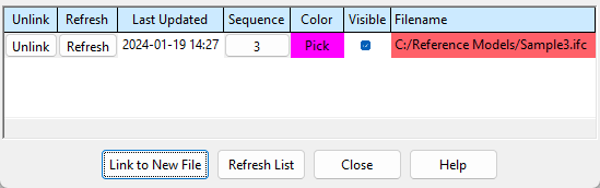
File name highlighting: Red highlighting of a file name indicates that the file has been deleted or moved from its original location. When this happens, the reference model member continues to exist in Modeling. To remove the reference model member, you can press Unlink.
Link to New File: Click the Link to New File button to import a DGN, DWF, DWG, IGES, STEP or IFC file as a reference model.
Note: Before clicking the Link to New File button, the reference model file needs to be placed in a folder that your workstation has access to. If you are importing a file other than an IGES file, you may also want to exit Modeling and use the Change File Sizes utility to allocate additional room for the 3D submaterials you will be importing. Since an IGES reference model will consist of only one member and one material, you probably will not have to Change File Sizes before importing it.
1 . Click the Link to New File button.
2 . A selection window opens. Note that you can choose to display DGN (.dgn, .DGN) or DWF (.dwf .DWF .dwfx .DWFX) or DWG (.dwg .DWG) or IGES (.igs, .IGS, .iges, .IGES) or STEP (.stp or .STP or .step or .STEP) or IFC (.ifc, .IFC, .zip, .ZIP, .ifcZIP, .IFCZIP, .IFCZIP) files. Navigate to the folder that contains the file you want to import, select the file, and click the Open button.
Alternative: Click the Cancel button to end the Link to New File operation.
3 . The Linked Model ... Options window opens. Click OK button when you are done with the options in this window.
Alternative: Click the Cancel button to end the Link to New File operation.
4 . A progress bar is displayed while the reference model is being imported from the file you selected. You may also get warning messages. A new entry will be made to the Filename column on the Reference Model Manager window.
Tip: To zoom into the reference model you just linked to or refreshed, select the reference model member in the Model Tree, then choose Navigate > Zoom to Fit.
This example shows an IFC reference model. You can tell because the reference model member is named after the IFC file name. Another indication is the multiple dummy materials that are attached to the member. If this was an IGES file, only a single dummy material would be attached to the member.
Refresh List: Click the Refresh List button to update the information shown on the Reference Model Manager window. This brings the window into the same state it would be in if you were to click the Close button and reopen it again.
For example . . .
Close: Click the Close button to close the Reference Model Manager window. Choices you have made on the window will continue to be applied to a reference model even after the window is closed. For example, if you assigned a color to a reference model, that reference model will continue to be displayed in that assigned color after you press Close.
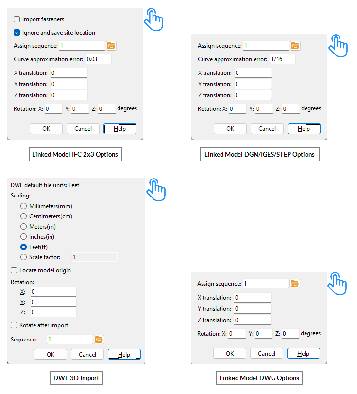
The Linked Model ... Options window
If this box is checked (
If the box is not checked (
Ignore and save site location: ![]() or
or ![]() . A site location is an offset to an IFC file's member coordinates. By default, this option is checked, since checking this box gets around the 100-mile limit for translation transformations.
. A site location is an offset to an IFC file's member coordinates. By default, this option is checked, since checking this box gets around the 100-mile limit for translation transformations.
If this box is checked (
If the box is not checked (
Assign sequence / Sequence: Any sequence name from the Sequence Names setup list can be entered here.
To assign the sequence, you can type in its name, or you can press the "file cabinet" browse button (
) and double-click a sequence name that is on the list.
The sequence entered here is reported in the Sequence column on the Reference Model Manager window. Assigning a reference model member a sequence gives you the ability to color code, isolate, or mask that member using Status Display > General status options > Sequence or Zone.
Curve approximation error: A positive distance that determines the number of polygons generated to represent curved surfaces.
A small Curve approximation error such as 1/32 inch results in a large number of polygons being generated to more accurately represent curved surfaces. Increasing the distance results in fewer polygons being generated and can potentially decrease Modeling memory use. The down side of increasing this distance is curved surfaces being generated less precisely.
X translation: 0 or a +/- distance. This option can be used to adjust the global X axis coordinate of the reference model. Translations may be up to +/- 1,000,000 inches (25,400,000 mm).
Entering a positive distance results in that amount being added to the X coordinate information that is in the reference model file.
Entering a negative distance results in that amount being subtracted from the X coordinate information in the file.
Tip: Performing Member Move/Stretch on a reference model member is another way to translate that reference model's location. Doing this also updates the translation field(s) in the Linked Model ... Options window.
Y translation: Same as X translation, except that the translation will be done with respect to the global Y axis. Translations may be up to +/- 1,000,000 inches (25,400,000 mm).
Z translation: Same as X translation, except that the translation will be done with respect to the global Z axis. Translations may be up to +/- 1,000,000 inches (25,400,000 mm).
Rotation(degrees): X and/or Y and/or Z rotations can be entered. These are global axes. Entering a positive number of degrees rotates the reference model counterclockwise about that axis. A negative number rotates it clockwise about the axis.
|
||||||||
| Tip: To tell which global axis is which in a particular Modeling view, you can add an axes box to your toolbar. | ||||||||


DWF Default File Units: read-only. This reports the units of measurement that are stored in the DWF file. In other words, this is the scaling that was used when the original DWF model was created.
Scaling: Millimeters (mm) or Centimeters (cm) or Meters (m) or Inches (in) or Feet (ff) or Scale factor. In most cases, you should select the units that correspond to the DWF Default File Units reported above. Doing so should result in the imported items being scaled to match members and materials in your 3D model. You should enter a Scale factor only as a last resort.
| Default Units | Scaling | Result |
| ' Millimeters ' | ' Centimeters ' | Scale is 10 times larger than if ' Millimeters ' had been selected. |
| ' Inches ' | ' Feet ' | Scale is 12 times larger than if ' Inches ' had been selected. |
If this box is checked (
If the box is not checked (
If this box is checked (
If the box is not checked (
OK closes the Linked Model ... Options window and applies the choices you made to it. See step 5 of the link/refresh procedure for more information.
Cancel ends the Link to New File (or Refresh) operation without generating (or regenerating) a reference model.
1 . Click the Manage Reference Models icon, which is pictured above. The icon can be found on the Tools page > Reference Objects section.
Alternative: Invoke Manage Reference Models using the Find Tool by searching the command name and clicking the icon, which is pictured above.
Learn more about alternative methods for launching commands.
2 . The Reference Model Manager window opens. Click the Link to New File button to import a new reference model or adjust the options for a previously imported reference model.
3 . Click the Close button to end the Reference Model Manager.
- Reference model member (member type to which a reference model attaches)
- Model Tree (lists visible reference models)
- Selection filters (All, Legacy default, Members, and Reference Model filters permit selection of reference models)
- DWF 3D Import (pressing " Link to New File " may be used to import a DWF file)
- Import Model (alternate way to import a DGN, DWG, IGES or STEP reference model)
- Move/Stretch Members (can be performed on a reference model member to relocate that reference model's position)
- Move/Stretch Members, Include Material

